


Meccanoid Hacks Pt. 1
Originally Posted: Oct. 22, 2022
Last Edited: Oct. 23, 2022 - 12:30 AM EST
Author: Mr. Siefen
Code Repo: https://github.com/mrSiefen/MeccanoidHacks
What is a Meccanoid?
Meccanoid is a series of Robotic S.T.E.M. Toys made by Meccano and Spinmaster. The robot toys were part construction kit, part programming toy, part robotic actor.

How Many Meccanoid Variants exist?
Created in the mid 2010s the Meccanoid Robots had 4 variants: G15, G15KS, 2.0 and 2.0 XL. G15 and the 2.0 are the SAME except 2.0 is slightly newer. G15KS and 2.0XL are the SAME except 2.0XL is also slightly newer. What separates the 2.0 and original series is color and the "Meccabrain" model. Newer Meccabrain's are compatible with older models and vise versa.

Let's Compare 'Em!
| G15 | 2.0 | G15KS | 2.0XL | |
|---|---|---|---|---|
| D.O.F. | 6 | 6 | 10 | 10 |
| Height | 2 Ft | 2 Ft | 4 Ft | 4 Ft |
| Servos | 4 | 4 | 8 | 8 |
| Drive Wheels | 2 | 2 | 2 | 2 |
| LEDS (total) | 8 | 8 | 12 | 12 |
| Meccabrain | 1.0 | 2.0 | 1.0 | 2.0 |
| Connectivity | ||||
| Hackable | ✓ | ✓ | ✓ | ✓ |
How Can They be "Hacked"?
While we cannot modify the existing "Meccabrain", we can directly control the servos, LEDs and motors. The servos and LEDs even have Arduino Compatible libraries! While it's not the easiest thing to find you can even find the original open source documentation, the WayBack Machine helped me out here. All of the Servos and LEDs are chainable in groups of 4 in a really clever method. All 4 modules in the chain share 1 PWM signal line and split it into 4 chunks.
Read through the PDF below to learn more! (I'm hosting this PDF copy since Meccano pulled their open source support).
What Hardware do I Need to Control my Meccanoid?
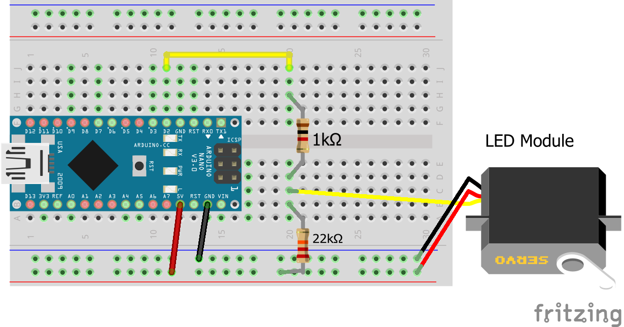
All Meccanoid modules have 3 wires, just like Servos. The red wire is 5V+, the black wire is Ground (GND), and the signal line is white (coming from LED module). The signal line is connected to any PWM capable Arduino pin, with the signal being divided down by a pair of resistors.
- 1x Arduino Microcontroller (Any 5V)
- 2x Resistors per module chain
- 1x 22k Ohm
- 1x 1k Ohm
- 3x Jumper Wires
- 1x Programming Cable
How Do I get the Meccanoid Arduino Libraries?
Even though you can track down the original Meccanoid library made by Meccano (again via the WayBack Machine), I do NOT recommend this library. Another Tech Enthusiast named Alex Frederikson on GitHub made a much improved library that works great! You can download the library here and follow the setup instructions to add it to your Arduino IDE.
I plan to write another customized version of this library later after implementing NeoPixel upgrades for the eyes. If you want to get "ahead" of the game you can download the FastLED and NeoPixel libraries through Arduino's Library Manager tool. I will also publish a PlatformIO compatible library as well as soon as the Arduino version is completed.
Creating your First Meccanoid Control Program
Alex's Test Program is great, but can feel a little overwhelming at first. I want to start a little slower, but you can run his default program with any 5V Arduino Board by just editing the pin variable to match your real world circuit.
For our first program we will only control the LED lights on the head. The Meccano LED Module can ONLY be the END of a chain. Since it's the easiest module to control and has the least risk of damaging something we will start there.
The SEMI_PSEUDO_CODE:
- Import the library
- Create eyes LED Module
- Create module chain
- Add eyes to chain
- Setup ( )
- Begin Serial at 9600 Baud
- Loop ( )
- Get updates from the chain
- If justConnected
- Set eyes to OFF
- If isConnected
- Set eyes to RED
First Meccanoid Control Program:
#include <Meccanoid.h>

/* typedefs for convenience */
typedef MeccanoLed   Led;

/* Note that their needs to be a 22k ohm pull-up resistor on chain input,
    * See https://www.mrsiefensrobotemporium.com/downloads/Meccano_SmartModuleProtocols_2015.pdf Smart Module Protocol
    * (bottom of PDF) for more details. */

/* PWM pin for LED */
int pin = 2;

/* define chain and PWM pin for it */
Chain chain(pin);

/* define modules to use and their positions */
Led eyes = chain.getLed(0);   // only thing on chain  (0)

void setup() {
    // startup serial
    Serial.begin(9600);
}

void loop() {
    // update chain to poll for input
    chain.update();

    if (eyes.justConnected()) {
        Serial.println("Led connected! Turning OFF");
        eyes.setColor(0, 0, 0, 0);
    }

    if (eyes.isConnected()) {
            eyes.setColor(8, 0, 0, 0);
        }
    }
}
Expanding your First Meccanoid Control Program
So we've set the eyes to red. Cool beans dude, big deal. That's baby stuff!

Don't worry, now we can get to the fun stuff! Next we're gonna make the eyes change color based on Serial input. The Meccano LED Module supports a total of 256 colors (some are really similar). We control those colors with the setColor(red,green,blue,fade) method
The SEMI_PSEUDO_CODE:
- Import the library
- Create eyes LED Module
- Create red, green and blue variables
- Create module chain
- Add eyes to chain
- Setup ( )
- Begin Serial at 9600 Baud
- Loop ( )
- Get updates from the chain
- If justConnected
- Set eyes to OFF
- If isConnected
- Wait for user input for RED
- Wait for user input for GREEN
- Wait for user input for BLUE
- Set eyes to RED, GREEN, BLUE values
Expanded First Meccanoid Control Program:
#include <Meccanoid.h>

/* typedefs for convenience */
typedef MeccanoLed   Led;

/* Note that their needs to be a 22k ohm pull-up resistor on chain input,
      See https://www.mrsiefensrobotemporium.com/downloads/Meccano_SmartModuleProtocols_2015.pdf Smart Module Protocol
      (bottom of PDF) for more details. */

/* PWM pin for LED */
int pin = 2;

/* Red, Green, Blue and userInput Variables */
byte red = 0;
byte green = 0;
byte blue = 0;

/* define chain and PWM pin for it */
Chain chain(pin);

/* define modules to use and their positions */
Led eyes = chain.getLed(0);   // only thing on chain  (0)

void setup() {
  // startup serial
  Serial.begin(9600);
}

void loop() {
  // update chain to poll for input
  chain.update();

  if (eyes.justConnected()) {
    Serial.println("Led connected! Turning OFF");
    eyes.setColor(0, 0, 0, 0);
  }

  if (eyes.isConnected()) {
    // Get the users input
    Serial.print("Enter Red Value: ");
    while (Serial.available()==0) {  }
    red = Serial.parseInt();
    Serial.println(red);
    Serial.print("Enter Green Value: ");
    while (Serial.available()==0) {  }
    green = Serial.parseInt();
    Serial.println(green);
    Serial.print("Enter Blue Value: ");
    while (Serial.available()==0) {  }
    blue = Serial.parseInt();
    Serial.println(blue);
    Serial.println("Setting Colors: " + String(red) + ", " + String(green) + ", " + String(blue));
    eyes.setColor(red, green, blue, 0);
    Serial.println("");
  }
}
What's Next?
Now that we know how to build a circuit that can control the Meccanoid Modules, what can we do? We can currently control the RED, GREEN, BLUE colors of the eyes. That's great but the whole point of Meccanoid is controlling the limbs. Don't worry that's the first step of part 2! If you want to look ahead I highly recommend taking a peak at the "meccanoid_test.ino" example file included in Alex's library. See you in part 2 for more!
